Installing a Trailer wiring harness is more than matching colored wires. It creates the electrical link between a towing vehicle and its trailer lights, brakes, and auxiliary circuits. A loose ground can leave the lamps dark. A reversed turn signal can confuse drivers behind you. Small mistakes become serious at night, in rain, or during sudden braking.
Industry standards provide a reliable starting point. SAE J560 defines the functions and terminal layout of common seven-way trailer connectors in North America. ISO 1724 provides a related seven-pin reference for many international applications. NHTSA safety guidance also emphasizes visible brake lamps, turn signals, and rear lighting for safer trailer operation. These sources do not replace the vehicle manufacturer’s wiring diagram. They help prevent guesswork.
This guide explains how to choose, route, test, and secure a Trailer wiring harness properly. You will see practical details, including waterproof connectors, heat-shrink tubing, fuse protection, and frame-safe cable routing. A multimeter matters. So does patience. Many installations fail because the installer trusts wire color alone or skips the final load test. That is a weakness worth admitting. Vehicle wiring systems vary, and some newer models require a powered converter or electronic module. Confirm the vehicle’s specifications before cutting anything. Then test each function with a second person watching the trailer lamps. A clean installation should survive vibration, spray, and repeated hitching without exposed copper or dangling wires. Safety is not achieved by appearance. It is verified at the connector, the lights, and the road-ready trailer.
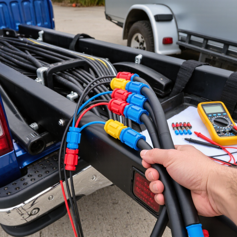
Before installing a trailer wiring harness, identify the trailer’s wiring system. Count the connector contacts and inspect the socket shape. A flat four-way plug usually carries ground, tail lamps, left turn, and right turn signals. A seven-way connector adds circuits for electric brakes, battery charging, and auxiliary power. SAE J560 defines the common seven-contact arrangement used on many heavy-duty trailers, but color codes can vary. Never trust color alone.
Bring a digital multimeter, circuit tester, wire stripper, crimping tool, heat-shrink tubing, electrical tape, cable ties, and a small wire brush. A wiring diagram is essential. NHTSA’s Traffic Safety Facts publications consistently identify lighting and signaling as important crash-avoidance controls. That supports careful testing, not guesswork. Check the vehicle socket first. Measure ground continuity, then test each circuit with the vehicle lights and indicators activated. Keep the connector dry.
Look closely at the trailer’s frame and junction box. Rust can create resistance. Poor grounding is common. I once found a clean-looking wire with corrosion hidden beneath its insulation. It passed a quick visual check but failed under load. That mistake changed my process. Test every circuit twice, including the brake controller line if equipped. SAE J1128 guidance also distinguishes automotive wire constructions by insulation and temperature performance. Use suitable cable, protect exposed connections, and leave enough slack near the coupler for turning movement. Do not seal a connection before testing it.
Identify the trailer wiring system before installation. The chart compares common wiring configurations by the number of electrical circuits they typically support.
Typical tools: wire stripper, crimping tool, multimeter, electrical tape or heat-shrink tubing, cable ties, and a socket set. Match the harness to the trailer connector and verify every circuit with a multimeter before towing.
Before installing a trailer wiring harness, park on level ground and switch off the vehicle. Engage the parking brake. NHTSA’s 2022 Traffic Safety Facts recorded 5,837 deaths in crashes involving large trucks, reminding us that small connection errors deserve serious attention. Inspect the tow vehicle’s rear area for dirt, corrosion, crushed wires, or previous repairs. A clean work area prevents false diagnoses later.
Open the vehicle’s service manual and identify the approved wiring connection points. Many vehicles provide a dedicated connector near the rear cargo panel, while others route separate turn, brake, tail, and ground wires. Do not guess by color alone. Use a digital multimeter and verify each circuit with the ignition, brake pedal, and turn signals activated. Keep the probe steady. I have seen “working” lights fail after vibration exposed a weak ground.
Match the connector layout with the applicable standard, such as SAE J560 for common seven-way systems or ISO 1724 for certain trailer arrangements. Confirm the ground wire reaches clean, unpainted metal or the specified grounding point. Remove oxidation gently, then protect the connection from water without trapping moisture. Leave enough slack near the hitch, but keep wires away from exhaust heat, suspension movement, and sharp edges. A routing plan can look obvious and still be wrong. Recheck every circuit with the trailer attached, then inspect the harness after a short, controlled drive.
How to Install a Trailer Wiring Harness Properly?
Install the Trailer Wiring Harness Step by Step
Installing a trailer wiring harness properly begins with careful preparation. Park the tow vehicle on level ground and switch off the ignition. Gather a circuit tester, wire stripper, crimp connectors, heat-shrink tubing, and cable ties. Read the harness instructions before touching any wires. Vehicle wire colors can differ.
Locate the rear lighting wires and test each one with the circuit tester. Identify the left turn signal, right turn signal, brake light, and running light circuits. Do not rely on color alone. Disconnect the battery if the instructions require it. Connect each harness wire to the matching circuit, then seal every connection against moisture. Use a clean, unpainted metal point for the ground wire. Secure the harness away from exhaust heat, sharp edges, and moving suspension parts.
Test it twice.
Plug the trailer into the socket and check the running lights, brake lights, turn signals, and hazard lights. A weak ground may cause dim lights or strange flashing. Check the ground connection before replacing parts. I have seen installers tighten a loose wire and assume the job was finished. That shortcut caused repeated failures in rain. It is better to inspect every connection again, even when the lights work. Confirm that the socket is firmly mounted and that the cable has enough slack for turns. Follow applicable local towing and lighting requirements before using the trailer on public roads.
A trailer wiring harness is not finished when every lamp works. Safe operation depends on how the cable is secured, protected, and routed. In field installations, movement near the drawbar is a common weak point. Use an abrasion sleeve, then fasten it with UV-resistant ties every 300–450 millimeters. Keep the harness away from exhaust heat, sharp brackets, suspension travel, and pinch points. Leave a gentle service loop near the connector, not a hanging coil.
Disconnect power before routing. Inspect the vehicle connection for corrosion, too. A clean ground matters. SAE J1128 sets requirements for low-voltage road-vehicle wires. Compliant cable still fails when crushed or overheated. NHTSA’s Traffic Safety Facts 2022 recorded 42,514 deaths across approximately 5.93 million police-reported crashes. The report does not isolate trailer-wiring faults. However, it reinforces the value of dependable lighting. Test the tail, stop, turn, and hazard functions with the trailer attached. Check them again after the first short trip.
Water finds small gaps. Seal entry points with a weatherproof grommet, and route connectors downward or keep them capped when unused. Do not use electrical tape as the main support; heat and moisture loosen it. A rushed final inspection is a mistake I still see in workshops. Slow down. Tug each fastener lightly, inspect fresh rubbing marks, and correct the route before the next load. FMCSA inspection guidance also treats lighting and electrical components as safety-critical equipment.
| Step | Installation Area | Recommended Standard | Installation Requirement | Verification Method |
|---|---|---|---|---|
| 1 | Vehicle Preparation | 12-volt electrical system; ignition switched off | Disconnect the negative battery cable before working on vehicle wiring. Confirm that the vehicle and trailer wiring diagrams are available. | Ready Verify that no lights or accessories are powered during installation. |
| 2 | Connector Selection | Match the connector to the trailer functions | Use a connector with sufficient terminals for the required circuits, such as running lights, left and right turn signals, brake lights, ground, auxiliary power, and electric brakes. | Confirm that every vehicle circuit has a corresponding trailer connector terminal. |
| 3 | Wire Gauge | 18 AWG for low-current lighting; 10–12 AWG for higher-current auxiliary or brake circuits | Select wire size according to circuit load and cable length. Use heavier wire for electric brake and auxiliary power circuits to reduce voltage drop. | Compare the selected wire gauge with the circuit current and total run length. |
| 4 | Circuit Protection | Fuse or circuit breaker rated for the connected load | Protect auxiliary power and other separately supplied circuits near the battery. Do not install a fuse larger than the wire or equipment rating. | Inspect the fuse rating and verify that the fuse holder is securely mounted and weather protected. |
| 5 | Ground Connection | Dedicated ground wire connected to clean vehicle metal | Run a dedicated ground conductor through the harness. Attach it to a clean, paint-free metal point or the designated ground terminal rather than relying only on the trailer frame. | Perform a continuity test between the connector ground terminal and the vehicle chassis. |
| 6 | Harness Routing | Clear of heat, sharp edges, suspension, steering, and moving parts | Route the harness along existing protected wiring paths where possible. Keep wiring away from exhaust components, rotating shafts, hinges, springs, and areas with suspension movement. | Turn the steering and move the suspension through its normal range to confirm adequate clearance. |
| 7 | Mechanical Protection | Split loom, abrasion-resistant sleeve, and rubber grommets | Protect exposed wiring with loom or sleeve. Install rubber grommets wherever the harness passes through metal panels, and seal openings against water and dirt. | Inspect the entire route for exposed insulation, unsupported spans, or contact with metal edges. |
| 8 | Fastening | Cable ties or clamps at regular intervals | Secure the harness so it cannot sag, drag, or pull on the connector. Leave enough slack near the hitch for turning, but prevent the cable from touching the ground. | Pull gently on the harness and inspect each attachment point for movement or sharp contact. |
| 9 | Splices and Terminals | Sealed crimp connectors or soldered joints with heat-shrink protection | Make splices in protected locations. Use properly sized terminals, create firm crimps, and seal connections against moisture. Avoid twisting wires together without a mechanical connector. | Perform a light pull test on each terminal and check for exposed copper or loose insulation. |
| 10 | Connector Mounting | Secure, accessible, and protected from impact and road spray | Mount the trailer connector firmly near the hitch. Position the opening to minimize water collection and provide enough cable length for normal trailer articulation. | Confirm that the connector cannot rotate excessively, contact the road, or be struck by the hitch. |
| 11 | Polarity and Function Test | Test every circuit before towing | Reconnect the battery and test tail lights, left and right turn signals, brake lights, ground continuity, auxiliary power, and electric brake output when equipped. | Use a multimeter or trailer-circuit tester and compare each connector terminal with the wiring diagram. |
| 12 | Final Safety Inspection | No loose wiring, damaged insulation, overheated components, or warning indicators | Inspect the completed harness after a short test drive or vehicle movement. Recheck fasteners, connector condition, fuse protection, and clearance from hot or moving parts. | Approved Trailer lights operate correctly and the harness remains secure under normal movement. |
Testing every trailer light is more important than simply connecting the harness. A loose ground can make several lights flicker together. I check the connector, ground wire, and frame attachment before chasing individual faults. Use a multimeter to confirm power at the connector. Then test running lights, brake lights, turn signals, hazard lights, side markers, and reverse lights.
Test under load.
The Commercial Vehicle Safety Alliance reported 48,761 Level I inspections during its 2024 International Roadcheck. Lighting violations represented 13.3% of out-of-service vehicle violations. That figure shows why a visual check alone is not enough. Connect the trailer to the tow vehicle, turn on each function, and watch for dim output or delayed response. A helper makes this safer and faster.
If one lamp fails, inspect its socket, bulb, connector pin, and local ground. If several lamps fail, measure the main ground and inspect crushed insulation near the tongue. Corrosion often hides inside sealed-looking connectors. I have also found wiring tied too tightly against sharp steel. It worked briefly, then failed after vibration. Protect exposed sections with suitable conduit, but do not bury a poor connection. After repairs, repeat the full lighting test, including the brake pedal and hazard switch. Keep a simple test record; it may reveal a recurring fault later.
MSIRobot